Wednesday, June 30, 2010
Thursday, June 24, 2010
Homemade Computer Microphone
(1) Electret Microphone (We have used CZN-15E) also see here
(2) Stereo jack pin
(3) Ceremic capacitor of 0.1 uf * non electrolytic
and about 1.5 meter single core shielded wire . construct it and enjoy!
Wednesday, June 23, 2010
Resources
Saturday, June 19, 2010
Calculation of Torque and RPM
Calculation of Torque and RPM
If you are comfortable with basic mathematics and wish to know the torque and rpm you require for your motor then this section is for you [or you can calculate it from the ‘motor calculator’ which will be uploaded soon]
Calculation of torque:
Let’s calculate the torque you require for your bOt to move. Consider the example given below of a bOt for understanding.
- No of wheels = 3 with differential drive
- No of motors = 2
The bOt is front wheel driven and has a rear castor wheel.
- Coefficient of friction = 0.6 and radius of wheel = 3cm
- Weight of bot (W=mg= 20N) (f= friction, N= normal)

When the bOt is accelerating in the forward direction, the friction acts in the forward direction on the front wheels (the friction is the force that drives the bot, just like you can’t move without friction) and on the rear castor wheel the friction acts in opposite direction (see figure above). Assuming that we have an impending motion i.e. the torque is just sufficient to start the bOt. Following are the equations of motion:-
N1+ 2*N2= W
f2x* r – τ= 0
Since there is an impending motion hence f2x= µN.
For a motor the impending torque should be able to overcome the static friction torque. After this, the torque required for rotating the wheels of bOt reduces and the rpm of motor will increase, hence the speed of bOt.
N= W/3 (considering that weight is equally distributed)
µ*W/3*r- τ=0
0.6*(20/3)*0.03- τ=0
τ= 0.12N-m or 1.2kg-cm
It has been assumed that the tyres can provide maximum grip or the traction force. To understand this concept consider the following example. Suppose your car is moving on mud, it will be very difficult for you to control the car due to slippage due to insufficient grip. From kinematic analysis it is seen that the maximum traction force is equal to the frictional force.
It is advisable to buy a 'high torque' motor as it can carry more load, move on higher slope and also if you have a rough track (that has wet mud, gravels, etc). Although this is a simplified model yet approximate values of torque (close to actual values) can be calculated.
Calculating the rpm of motor:
What should be want the maximum speed of your bOt to be? Do you know beyond a certain speed you won’t be able to control your bOt. Let’s calculate this speed.

Consider an example of an arena where the track is designed as shown in the above figure. Suppose the maximum speed of your bOt is 0.5 m/s and it transverses through the straight track of length 2 metre, the time taken is approximately around 4-6 seconds. It is believed that this is an optimum speed for the bOt.
Speed of bot= rpm of motor* radius (while moving forward)
0.5(m/s) = ω * 0.03(m)
ω= 17 (rad/s) = 17 * 60 /2π (rpm) = 160 (rpm)
Still rpm upto 300 is comfortable or rather controllable. If you feel that the rpm of your bOt is difficult to handle then you should choose a lower voltage rating.
Speed of bOt = (speed of left wheel + speed of right wheel)/2
When moving forward: -
speed of left wheel = speed of right wheel
Now while taking the turn of radius 20cm (see figure above) you will obviously switch off one motor.
Here the speed of right wheel = 0m/s
Therefore, speed of bOt = speed of left wheel
=> speed of bOt = 0.5(m/s)/2
This means that you will approximately take 1.2s to take the turn. You can do a similar analysis of your own bOt with different specifications.
http://www.botskool.com/tutorials/mechanical/calculation-torque-and-rpm
Sunday, June 13, 2010
Valve Radio Receiver sets
All Valve Radio Receiver sets are AM band (medium wave, short wave) old valve type
- 3 Bands 5 Valves Radio Receiver
- A set of 5 valves -U series A.C./D.C.
- Radio Parts fitting on chassis
- AC/DC 3 Band 5 valve
- Phillips radio receiver model number B2CA37U
- Murphy Radio Receiver Model Number TAO 776 (4Band 6 Valves)
- National Radio Receiver Model Number EXCOU 775
- GEC Radio Receiver Model Number
- HGEC Radio Receiver Model Number
- Radio coils and pack
- RF Amplifier ,Mixer, Oscillator
- AC/DC Valve Datasheet
- AC Valve Datasheet
Tuesday, June 8, 2010
Sunday, June 6, 2010
Parallel Track: Vehicle Tracking php application
Parallel Track: Vehicle Tracking php application
Parallel Track: Vehicle Tracking php application - [Link]
Wednesday, June 2, 2010
Although i linked to some DIY tutorials on printed circuit board making in the past, i decided to write my own tutorial to cover all the bits and pieces so that any beginner with no knowledge can obtain a PCB using the photo etching method. Lets start with the tools and materials i used:
- Canon MP160 Ink-Jet Printer
- Transparent paper for Ink-Jet printer
- Photo PCB (this type of PCB already has that photo-resist layer applied on it )
- UV Exposure unit
- Developer (I used this custom PCB developer)
- Ferric Chloride
- Acetone
- A piece of glass (preferably taken from a photo frame)
- Electric Driller
Read Full story here : http://www.youritronics.com/diy-printed-circuit-board-using-photo-etching-method/
Tuesday, June 1, 2010
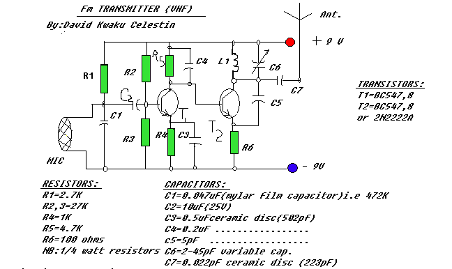
Portable FM transmitter

Read full story here http://www.epanorama.net/zen_schematics/Circuits/rf/fmtx_dc.html
Floodfill Algorithm
Download tutorial on Floodfill Algorithm from here (Click)
More Here http://www.me.iitb.ac.in/~adeshmukh/floodfill.php
Simple Water Level Indicator cum Alarm
Get Electronics component online In India Visit www.onlineTPS.com
 Get Electronics component online In India Visit www.onlineTPS.com
Simple Water Level Indicator cum Alarm
IR Sensor
Full story here
http://www.pages.drexel.edu/~pyc23/ir_sensor.html


